Paper Title: Deep-learning-based deflectometry for freeform surface measurement
Source: Deep-learning-based deflectometry for freeform surface measurement
Jinchao Dou, Daodang Wang, Qiuye Yu, Ming Kong, Lu Liu, Xinke Xu, and Rongguang Liang, “Deep-learning-based deflectometry for freeform surface measurement,” Opt. Lett. 47, 78-81 (2022)
Summary: The authors have developed a neural network methodology to reconstruct surfaces from a deflectometry measurement. They determine that the neural network is more resilient to noise and geometry errors when reconstructing a freeform surface as compared to typical reconstruction done by integrating slopes using Southwell integration.
Full Review: I love deflectometry (you may have noticed), and I think I have a decent grasp on the topic, so it is always a pleasure to read research papers in this area. On the flip side, I am skeptical of many ML/AI/Neural Net research articles, in part because often I find the authors don’t do a particularly good job of conveying what they actually did, how they did it, or that they were aware of clear possible biases imparted.

This is my reaction when I see machine learning work. I also am about as competent with respect to machine learning research as Andy.
Also, to toss in a third bias, I hate jargon heavy long papers. They suck to read, they are unnecessarily time consuming, and I tend to think that authors are simply trying to pad their papers with long, unintelligible fluff to make the reviewers think that the work is in fact so mind-blowingly impressive that even if we are confused it’s probably so good we should just approve it. This paper is an Optics Letters paper, which are required to be short, sweet and to the point. Thus, another point in the author’s favor.

Optics Letters papers are seriously great. Short and sweet. Also great to write, it really makes you write in an efficient way.
What is the problem the authors are trying to solve?
On to the review, the authors note that deflectometry is pretty great, but man it sure is a pain calibrating everything, making sure you have the geometry right, and at the end of the day what happens if you have noise or a discontinuity? Problems, that’s what!

As the authors state:
These methods work well for continuous surfaces with integrable slopes; however, errors occur when there is noise or a discontinuity (such as a scratch or stain) in the surface. Another problem that integration reconstruction algorithms cannot avoid is system geometrical error, which can lead to an obvious measurement error in the final result.
So, the problem statement is, we need a fast, easy, and resilient way to reconstruct surfaces from deflectometry that can accommodate noise and geometry errors from the measurement (note, I left off discontinuity issues as despite mentioning this as a problem, the authors don’t actually show their method does anything to address it).
How fatal are these problems for deflectometry?
They have a point. However, it is common to disambiguate geometry, noise, and discontinuity errors into their own classes. For example, Aftab et. al., addressed dealing with discontinuous data, such as when there is a scratch, or the aperture is obscured, fiducials, etc., by using Chebyshev gradient polynomials [1].
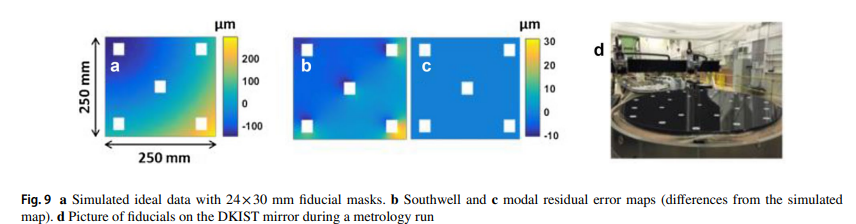
Figure 9 from Aftab [1]. Notice that discontinuous data from fiducials leads to a garbage reconstructed surface using Southwell integration, but high order modal G polynomials that she describes work great!

When it comes to geometry, the authors describe how to resolve the problem:
To achieve the effective calibration of system geometrical error, high-accuracy third-party measuring instruments for system geometry measurement and additional computer-aided calibration techniques are required. The calibration process is generally quite laborious, complicated, and time consuming, and there is still, inevitably, measurement uncertainty.” [emphasis added by me]
This is a true but trivial statement. Without going on a philosophical rant, all measurement systems include measurement uncertainty. The goal is to knock down your uncertainty below the level of accuracy that you need to know. For optics this tends to be in the range of single nanometers to maybe on loose things hundreds of nanometers. It is also, pending the optic and requirements, really important to know your uncertainty. If I promise someone an optic that is accurate to their shape requirement to the nanometer level, I need to know my systematic uncertainty is below that level. This is really important and I will bring it up later.
We also know that we can knock down geometry uncertainty to astonishingly low levels for deflectometry, it just may be brutally tedious [2].
Huang et. al., forever ruining the excuse that nanometer level calibration is impossible and making the rest of us look lazy. Image credit Huang, et. al., [2]
So why should we care as readers?
If you use deflectometry noise and geometry issues are a huge pain. You always need to be aware of them, calibration in general is time consuming and not super fun, and we all want more accurate results that are easier to obtain.
What did the author’s do?
Dou, et. al, created a:
deep-learning based deflectometric method is proposed for the accurate measurement of freeform surfaces. A Deflectometry-UNet (D-UNet) network is devised for freeform surface reconstruction. Full-scale skip connections are adopted to acquire full-scale image information for different layers in the proposed D-UNet network architecture, which can substantially improve the stability of the network and greatly enhance the surface reconstruction accuracy. With the proposed D-UNet, the deflectometric testing system is insensitive to noise and can even resist the influence of system geometrical error
In layman’s terms, they made a neural net that lets you send in measurement data from a deflectometry measurement, and you get a nifty reconstructed surface that is accurate. No need to unnecessarily hassle with complicated calibration steps or worry about noise. You do still have to worry about discontinuous data however apparently, but whatever, don’t look a gift horse in the mouth.

On one hand, great! I don’t do deflectometry research actively anymore, but when a did boy would I have welcomed a tool that could save me hours of calibration steps, frustration at trying to tease out where the noise and geometry errors were coming from in my system, and how to address them in the final processing of the data. On the other hand, I am biased against AI/ML/Neural Nets, and if you tell me you trained something to be resilient against noise and geometry errors, my immediate assumption is your system is going to confuse real surface data (like tilt, defocus, or astigmatism for example) as geometry errors. Or high frequency surface features as noise. And then I am going to be highly skeptical and uncertain that the reconstructed surface is actually what I measured, as opposed to what the neural net thinks I measured. Again, I am biased here.
How they did it:
Things in the general realm of AI/ML/Neural Nets always remind me of frameworks for javascript. I know javascript is a programming language. I can learn javascript. But until I became really familiar with javascript, every framework sounds like almost unintelligible, stand alone unique things. This is how I feel when I read about some new neural net or AI framework or package.

Really trying to put in the work to anger both the front-end developer and machine learning communities here.
Anyways, the authors made a simulation of a phase shifting deflectometry system. They traced rays from their camera model to a surface with known surface deformations and recorded the final ray locations, after reflection from the surface, at the screen. They then repeat the process for an ideal surface, they can get a “virtual “null””. Basically, the ray intersection points on the screen for your real system, colloquially called the ‘spot diagram’ for deflectometry, can be compared to the spot diagram from an ideal system, and the ray deviation, on a ray to ray basis, tells you how off your tested surface is from your ideal surface in the slope domain.
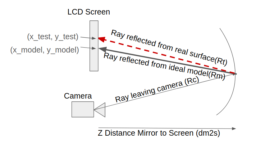
A quick cartoon of what a deflectometry system looks like as described in the paper.
The x and y slope errors of the measured surface as compared to an ideal surface, are:
And that covers the math from the deflectometry perspective. This is important because it is the metric by which the neural net evaluates the deflectometry system.
For the neural network, they create the above simulation, generate 11,000 freeform surfaces for the mirror, and ray trace them all to get both the test and model ray positions. They also state they incorporated system tolerances, which I don’t actually know what that means. Specifically, because I don’t want to misrepresent their work:
In order to validate the feasibility of the proposed method for freeform surface measurement without any loss of generality, 11000 datasets of freeform surfaces represented by Zernike polynomials and their corresponding slope data were randomly generated. The tolerances of the testing system geometry were also added. The maximum peak-to-valley (PV) and RMS values of the generated surfaces were 26.5317 and 4.3155 µm, respectively.
Then they calculate the surface slopes, which they call the derivative of the wavefront.
By comparing the image spot distributions corresponding to the tested element with and without surface errors, the wavefront aberration W(x, y) can be obtained according to the transverse ray aberration model, and we can calculate the surface slope difference (∆wx, ∆wy)
The specifics of the neural net as described by the author is as follows:
As shown in Fig. 2, the slope matrices (size: 64 × 64) in the x and y directions are first batch normalized before they go through the convolutional layer (kernel size is 7, stride = 1), the average pooling layer (pooling window 2 × 2, stride = 2), and the leaky rectified linear unit (ReLU) activation function layer sequentially in each downsampling step, in which the size of the feature map is halved and the image depth (number of image channels) is doubled. Similarly, the feature map is processed by the upsampling layer, the convolutional layer, and the leaky ReLU layer in each upsampling step, which ensures that the input data and output image are the same size. In contrast to a traditional UNet network, full-scale skip connections are applied to the designed structure to extract and incorporate multi-scale feature information from different layers, which can greatly enhance the reconstructed surface detail. When concatenating different layers, the parameters, including the size of the pooling window and the stride in the pooling layers, are specifically set to unify the sizes of the feature maps from different layers. After the last upsampling step, a 1 × 1 convolution of the feature map is implemented to resize the depth of the output surface map to 1.
And here is their picture of the neural net.
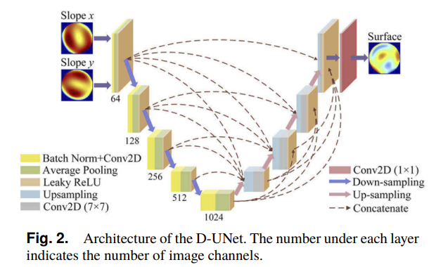
Excellent figure from the authors showing how the neural net is operating. There is a lot going on here but surprisingly easy to read. Image credit to the original paper.
The neural net then works to minimize the RMS error between the reconstructed surface and the nominal surface. The specific function is below:
How well does it work?
How does one evaluate a neural net? You train it to do operation x to datasets of y, then you evaluate its performance by having it do operation x to some nearly identical (but in fact different from) dataset to y. For this neural net, the first thing that jumps to my mind would be the idea to generate a new freeform surface, do the raytrace, and reconstruct the surface to see how far off it is from the nominal surface. That is what it is trained for. Here is deflectometry data, construct a surface from it, and adjust how that construction is done to minimize the error between the reconstructed surface and the real surface. This is also a gross oversimplification, if you actually want to learn from someone qualified how to train a neural net, see here.
The authors follow the same approach to begin with, make a freeform surface, but then importantly they added noise to the slope data from the deflectometry simulation.
To verify the performance of the proposed D-UNet under the influence of noise (such as system noise and vibration), additional Gaussian noise with an amplitude of 20 µrad was added to the slope data.
They then reconstruct the surface using a) the neural net and b) just simple southwell integration of the slope data. They find that the neural net reconstruction is about an order of magnitude more similar to the nominal surface than the southwell integration method. This is great news for the neural network and its ability to reconstruct deflectometry data when there is noise! Here is a figure from the paper showing how well it works:
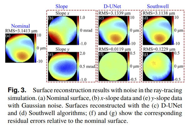
Figure from the authors showing the raw slope maps and the reconstructed surfaces and the error from the nominal surface. The neural net error is clearly better than the southwell. Image credit to the paper authors.
Specifically, the authors state:
there is an obvious residual error with a RMS of 0.1229 µm in the surface reconstruction obtained with the Southwell algorithm. However, the reconstruction achieved with the D-UNet is still robust in the presence of noise, with a RMS of 0.0119 µm.
They additionally wanted to show how excellent the D-UNet works for scenarios where the deflectometry data had geometry errors. Specifically, they would add 2 mm of x lateral displacement and 1 degree of tilt about the y axis to the simulated optic. They then run the simulation, get slope data, and again do the reconstruction with a) the D-UNet and with b) southwell integration.
Once again, D-UNet reigns supreme. Again, it is about an order of magnitude more accurate to the nominal surface in terms of RMS error. See below:
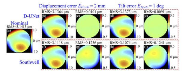
Authors show that the D-UNet more accurately reconstructs the surface as compared to straightforward southwell integration of the slopes. Top row is the D-UNet result, bottom is the Southwell result. Image credit to the original paper.
They also show the Zernike term fitting from terms Z5-Z37. Basically below Z16, only Z14 and Z9 match the nominal surface for Southwell integration. Above Z16 they all match well. For the D-UNet basically all of the terms match the nominal surface well.
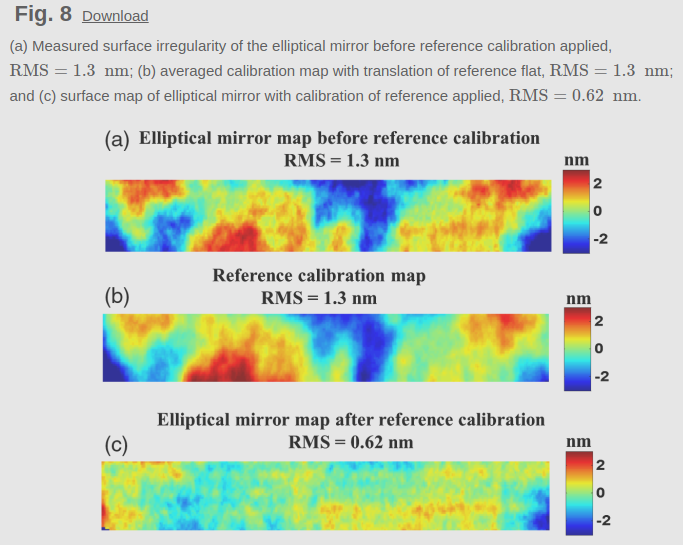
They also compare it to other deep learning methods, D-UNet is better than U-Net and ResU-Net. Finally they compare the D-UNet results for a real experiment. They measure a surface with an interferometer, then with a deflectometry system, and reconstruct it with the D-UNet and Southwell Integration of the slope data.
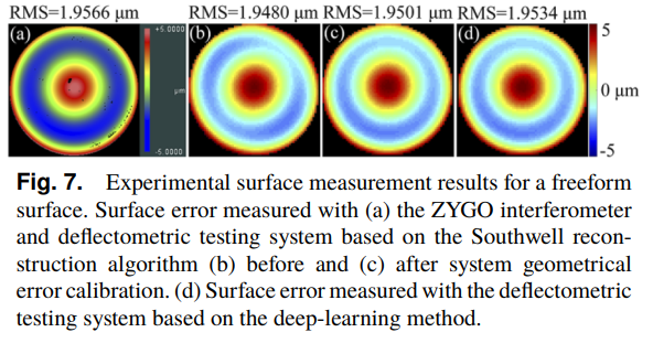
Authors demonstrate again that even for a real experiment the D-UNet reconstruction is better than a surface reconstructed via Southwell Integration of the slopes both before and after calibration. Image credit to original paper authors.
Conclusion: D-UNet works great, it is consistently better than Southwell Integration, and probably makes the scientist doing the measurements less frustrated at the world because they don’t have to bother with calibration. Incredible. Story is over, right?
What would I have expected to happen?
If I add gaussian noise to slope data, when I integrate it I end up seeing high frequency surface features that are not real in the final data. You can run a high-pass filter on the data and it becomes very clear. Also, in my experience gaussian noise has a small contribution to the final error, particularly RMS error.
If I have displacement or tilt error in my system that I didn’t calibrate for, I get tilt, astigmatism, and a few higher orders of Zernike terms present in my reconstruction. Like, you get a huge amount of astigmatism and tilt. For example, here is some early research work where I removed Zernike terms 1 through 4 (piston, tip, tilt, and defocus) from the reconstructed surface and compared it to an interferometry measurement.
Interferometry measurement on the left, deflectometry reconstructed surfaces on the right and center. Notice the huge amount of astigmatism? Tilt is removed, believe me it was large.
I would also expect there to be highly different reconstructed surface errors in the presence of gaussian noise in the slope data and geometrical errors due to lateral displacement and tilt errors, and those errors would be of very different magnitudes.
I don’t see any of the above in the results, which is confusing to me. However, I notice that the expected error is present in the real world test of an optic, and that with calibration the error I was expecting goes away in the reconstructed Southwell data. The final reconstructed maps look very similar between the reconstructed surface with Southwell integration with calibration performed and the D-UNet of the data. There is an RMS difference to be fair, but the shape looks extremely similar.
What are my concerns?
As I said, I am biased against AI/ML/Neural Net research as I often worry about biases built into the model. In particular, I am concerned that the D-UNet is biased to reconstruct only clear Zernike features. Yes, these are what we often expect to see in a traditionally manufactured surface, but not in all surfaces. I also do not understand how it is compensating for noise or geometry errors. I don’t see anywhere that the authors imply they trained for compensation of these issues, but I will let someone smarter than myself address this issue. Lastly, I am going to present my chief concern. How do I know that the astigmatism I see in my final surface reconstruction is due to false geometry error, or because it is in fact a real feature? I only can be certain of the final shape if I know my system uncertainty sources and what levels they are at. D-UNet looks great at not having these shapes reconstructed, but I have no way of knowing if it is knocking out real surface features it assumes are due to geometry errors, or false features that instead are truly due to the geometry errors.

My mental picture of the D-UNet behind the curtains telling me in fact the surface feature is not real, and why it removed it in the final reconstruction. In ncase I didn’t say it before, I am unfairly biased against most machine learning papers.
To summarize:
- Why does the Gaussian noise not show up only as high frequency surface feature errors?
- Why do the geometry errors not show up more clearly as tip/tilt and astigmatic errors?
- Why are the reconstruction errors of such a similar magnitude when there is Gaussian noise vs geometry errors?
- How do I know the neural net is compensating noise or geometry errors correctly, instead of knocking out real surface features that if I would really want to know about?
- Did the authors remove Zernike terms in their surface reconstructions? It looks like terms 1-4 are removed, but it is never stated so it would be good to get some clarity here.
Conclusion
All of that being said, I am still really impressed and happy about this paper. The quality of the publication is excellent, the figures are great, and there is little work done in metrology and machine learning. Overall I am thrilled this group published their work, and I think it sets up more excellent work in the future. I don’t want to imply with my concerns that this is not good work. Due to the limits of a letter paper, there is a limit on how much you can cover. Instead, I hope the authors extend their work and I hope to see some of these points addressed in future work. Looking forward to hearing other’s thoughts, and hopefully someone with more expertise can push back on some of my neural net concerns (looking at you @Isaac, @henryquach, @hkang).
[1]Aftab, M., Burge, J.H., Smith, G.A. et al. Modal Data Processing for High Resolution Deflectometry. Int. J. of Precis. Eng. and Manuf.-Green Tech. 6, 255–270 (2019). Modal Data Processing for High Resolution Deflectometry | International Journal of Precision Engineering and Manufacturing-Green Technology
[2] Run Huang, Peng Su, James H. Burge, Lei Huang, Mourad Idir, “High-accuracy aspheric x-ray mirror metrology using Software Configurable Optical Test System/deflectometry,” Opt. Eng. 54(8) 084103 (5 August 2015) https://doi-org.ezproxy2.library.arizona.edu/10.1117/1.OE.54.8.084103
 ) .
) .