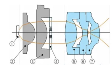
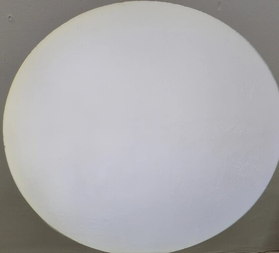
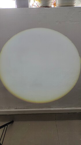
I designed a Gobo projector based on Kohler illumination(2 lenses for LED collimator + 1 film + 3 lenses for imaging). After production, due to the offset of the LED, half of the illumination spot appeared yellow, while the other half appeared blue. When the logo pattern occupies a significant proportion of the illumination spot, the colors appear uneven.
Due to difficulties in ensuring the position tolerance of LEDs and that the lens is very sensitive to LED misalignment, I hope to improve the tolerance capability of the lens through adjustments in optical design. Are there any solutions for this?
PS: LED emitting area 1mm^2. The misalignment of LED about the optical axis is about 0.2mm~0.3mm.
the total length of the lens is 20mm, the optical diameter of the lens is about 7 mm.
Thanks for the tag, @lrgraves !
@KeoNong any solution is probably going to decrease brightness, unfortunately. And even if perfectly aligned, I’d think there’d still be some color uniformity problems with just using lenses for optics because the color distribution of bare white LEDs is not uniform at all. Rays emitted close to the normal are super blue, and as you go farther from normal, they pass thru more phosphor, and those will be extra yellow. So, even if you’re projecting a defocused source image with Koehler, I’d imagine the output’s not gonna have perfectly uniform color.
It looks like your beam is a lot worse at the edges, so you could increase the spot size of your beam and then decrease diaphragm size to just clip that part out. But, as mentioned, this of course decreases brightness.
Otherwise, you can try adding diffusing elements near the source. A diffusing film or other plane element with diffusing texture placed between the LED and first optic can help sometimes. You may need to allow increased distance between elements at the LED side to allow for the color mixing to happen well enough to your liking. This method will also decrease brightness.
Another method that is probably less likely to help with your issue, as it’s primarily a misalignment problem, is treating the barrel. If the inside of your system is specular, uncoated aluminum, say, then you might be adding to the problem with weird stray light effects. Whenever color mixing is a concern, I try to avoid specular surfaces and materials (2 different things) in the surrounding geometry. So a rough, white coating, like a barium sulfate paint (BaS04+PVA+water – no MSDS so mix/use at your own risk) for high reflection (>98%) but also high diffusion is usually great for prototyping. Otherwise, a white plastic/3D printed barrel or mounts near and around the LED sometimes help, and can still get you at least around 80% reflectivity. If these parts are currently diffuse black, then of course, this would be even less likely of a factor, but adding in some extra nicely color-mixed light to your output by painting it white might improve overall appearance.
Playing with adding a simple diffusing element would be the best bet to start with!
Can you say what you’re building this for? Is it for funsies or a one-off system? Or do you intend to ramp it into high-volume production?
@SpireStarter Thanks for your suggestion!
Actually we’re building this for car logo projector(welcome light).
We considered about increasing the beam size. The new problem is HOW much size do we need to increase to ensure enough optical efficiency and uniform color, since LED misalignment does not just make the edge color uneven but also the central part.
We increased the beam size once.
figure above is the original beam size. The edge is worse because of the chromatic aberration at the edge of beam of the collimator. We think chromatic aberration mainly affects the edge of the beam (we call it yellow halo). Since 2-lenses collimator can’t eliminate chromatic aberration, we increased the beam size(the figure in the post). However, the uneven color distribution caused by LED misalignment still exists.
Adding a diffuser close to LED may encounter heat load problem especially for car-mounted.
The lens barrel is black PC+GF.

Here’s the lens structure

